Why Does Armored Cable Need Grounding? Common Mistakes to Avoid
Why Does Armored Cable Need Grounding? Common Mistakes to Avoid
In industrial power distribution, commercial buildings, underground pipeline networks, mines, and overseas engineering projects, armored cables are widely used in installation scenarios prone to crushing, puncturing, and gnawing damage, thanks to the mechanical protection provided by their steel tape, aluminum armor, or steel wire armor. Many electrical contractors, procurement engineers, and on-site construction personnel share a common question: Since the armor itself is merely a protective metal sheath, **why must armored cables be grounded?** Many on-site accidents stem from a lack of understanding of the principles behind armoring grounding, incorrect selection of grounding methods, and non-compliant installation connections.
This article will systematically explain the core purpose of armoring cable grounding, distinguish the differences in grounding logic between three-core low-voltage armored cables and single-core high-voltage armored cables, outline the most common grounding errors encountered on construction sites, and provide standardized best practices for installation. It also includes an FAQ section, making it suitable for Google SEO on international trade websites and electrical engineering blogs, and is intended for overseas electrical engineers, contractors, and cable procurement professionals.
What Is Armored Cable, and What Is the Function of the Armor Layer?
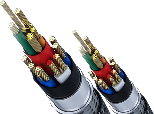
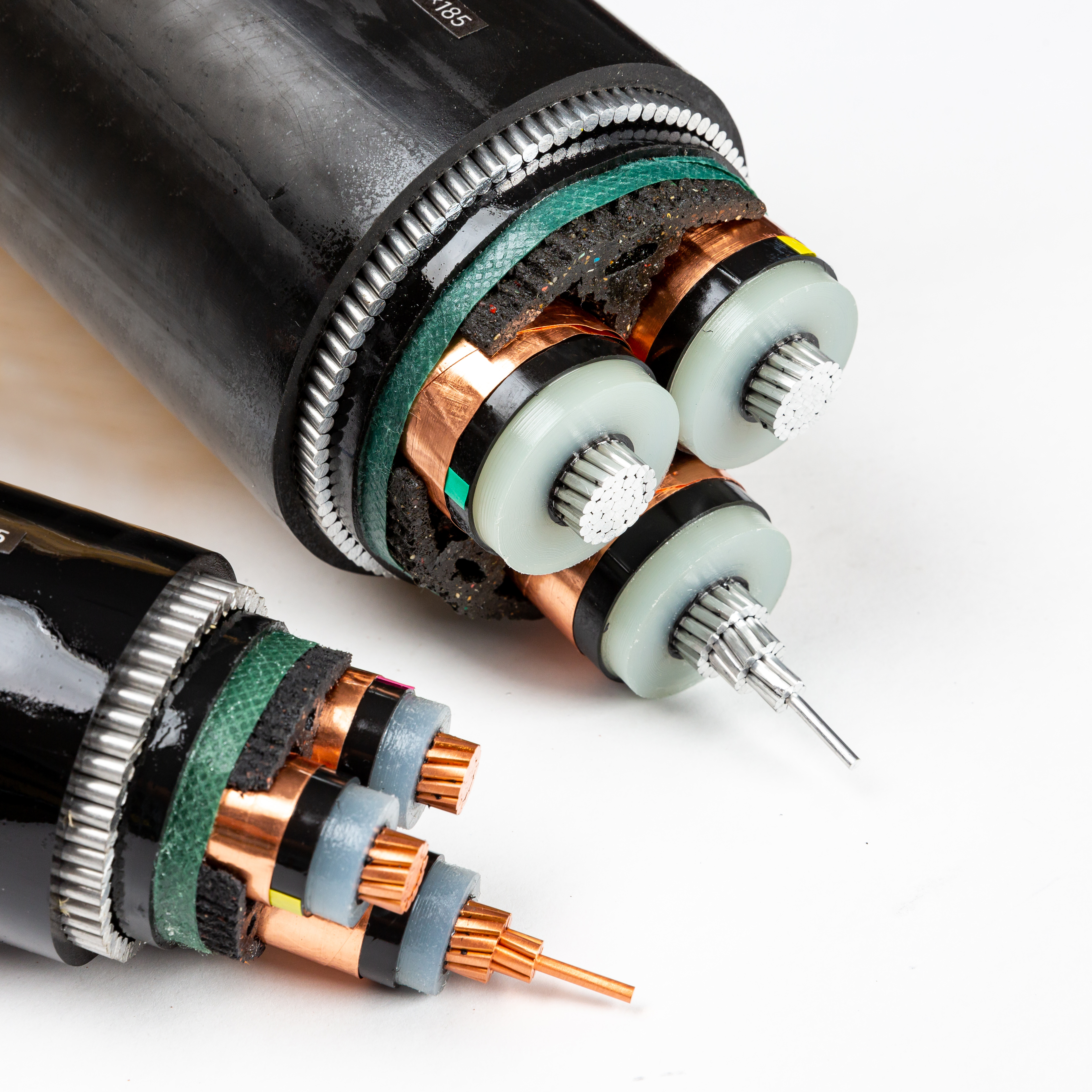
Armored cable refers to power or control cables that feature an additional layer of metal armor applied over the cable’s insulation and inner sheath. Common types include steel tape-armored (SWA, YJV22), steel wire-armored (AWA), and aluminum-sheathed armored (MC) cables. The primary function of armor is **mechanical protection**: in applications such as direct burial, cable tray installation, tunnels, outdoor environments, and mining sites, it prevents damage from rock compression, punctures during excavation, and animal gnawing, thereby protecting the internal insulated conductors from external forces.
Many people tend to confuse the two: armor ≠ protective earth (PE) conductor. Armor serves as a mechanical protective layer, whereas the PE conductor is a fault protection conductor. For certain certified MC cables, under conditions permitted by the NEC code, the armor may be recognized as an equipment grounding conductor (EGC); however, strict limitations apply. **It cannot be automatically assumed that all armor can replace a separate PE grounding conductor**—this is one of the most common misconceptions encountered in the field.
The metal armor layer has one key characteristic: it is a continuous, conductive metal sheath. When the internal insulation of the cable is damaged, or when alternating magnetic fields are generated by lightning surges or high-current operation, a potential is generated on this metal sheath. If the metal sheath is left floating and not grounded, dangerous voltages will accumulate, posing a risk of electric shock. This is the fundamental reason why the armor layer must be grounded.
The 4 Core Functions of Armored Cable Grounding
Provides a low-impedance fault current path during insulation breakdown faults to trigger protective devices
This is the most critical safety purpose of armored cable grounding. Long-term operation and aging, external punctures, or installation damage can cause the insulation of the main conductor to break down, resulting in direct contact between the live conductor and the metal armor. If the armor is not grounded, the entire armor sheath will become charged with the system’s operating voltage. When personnel touch cable terminals, cable joints, or metal cable trays, a fatal electric shock may occur; an arc between the armor and ground may ignite surrounding fill material or the cable outer sheath, causing a fire.
When the armor is reliably grounded, in the event of a short circuit between the conductor and the armor, the fault current will rapidly dissipate to ground or return to the power source’s neutral point via the armor and the grounding conductor. A sufficiently large fault current will trigger circuit breakers, fuses, and residual current devices (RCDs) to trip rapidly, cutting off the power supply, limiting the duration of the fault, and reducing the risk of electric shock and fire. NEC Article 330.108 specifically stipulates the continuity of the metal sheath of MC armored cables, with the purpose of ensuring the integrity of the fault current path.
Eliminating Induced Voltage Caused by Electromagnetic Induction to Protect Personnel and the Outer Sheath
When alternating current flows through a cable conductor, it generates an alternating magnetic field. This magnetic field links with the outer metal armor, inducing a voltage across the two ends of the armor.
- Low-voltage three-core armored cables: The vector sums of the three-phase currents largely cancel each other out, resulting in relatively low induced voltages; however, during load imbalances or short-circuit faults, the induced voltage can rise sharply;
- High-voltage single-core armored cables: The magnetic fields cannot cancel each other out. The longer the cable and the greater the load current, the higher the induced voltage in the armor layer. In long-distance single-core cables, the induced voltage at the ungrounded end can reach several hundred volts—enough to break down the outer sheath insulation, causing sheath breakdown and multipoint ground faults, which endanger the safety of maintenance personnel.
Grounding can clamp the potential of the metal armor layer to the zero potential of the earth, eliminating floating voltages and preventing a potential difference between the metal armor and ground.
Shielding Against Electromagnetic Interference to Ensure Stable Operation of Control and Instrumentation Circuits
For armored control and instrumentation cables, grounding the metal armor provides electromagnetic shielding. High-frequency electromagnetic noise generated by external inverters and high-power motors can couple into signal lines, causing sensor signal drift and PLC malfunctions. When the armor layer is reliably grounded, it diverts external electromagnetic interference fields into the ground, shielding the internal signal lines and ensuring the stability of low-voltage systems.
It is important to note that grounding strategies for power cables and signal cables differ. Signal armored cables typically employ single-end grounding to prevent ground loop currents; this common misconception will be explained in detail later in this document.
Discharging Lightning Surges and Switching Overvoltages to Protect the Cable System
When a cable line is struck by lightning or experiences grid-operated overvoltages, the impulse voltage couples to the metal armor layer. Ungrounded armor can accumulate transient high voltages, causing breakdown of the cable outer sheath and terminal sealing structures. The grounding system provides a discharge path to divert surge energy into the ground, reducing the amplitude of overvoltages, protecting the insulation of cable terminations and joint connectors from breakdown, and extending the cable’s service life.
 Grounding Methods Vary Significantly Among Different Types of Armored Cables (SEO Core Content)
Grounding is not a one-size-fits-all solution where “all armored cables are grounded at both ends.” The number of conductors and voltage rating determine the grounding scheme; selecting the wrong scheme can lead to more severe failures—a common pitfall for many engineers.
Low-Voltage Three-Conductor Armored Power Cables (0.6/1 kV, SWA steel tape armor, YJV22)
Applications: Building power distribution, plant power cables; three-phase three-conductor or 3+1, 3+2 configurations.
✅ Standard Practice: **The armor layer at both cable terminations must be reliably grounded**.
During normal operation, the magnetic fields generated by the three-phase currents largely cancel each other out, so grounding at both ends does not produce significant circulating currents. In the event of insulation breakdown, grounding at both ends provides a lower-impedance fault loop, ensuring rapid operation of protective devices. The armor should be connected using grounding clamps or copper braided grounding wires to the grounding busbar or the equipment enclosure’s grounding grid.
High-Voltage Single-Conductor Armored Cables (10 kV, 35 kV Single-Conductor)
Applications: Long-distance high-voltage transmission lines.
❌ Direct grounding at both ends is strictly prohibited!
Since single-conductor cables carry alternating current, grounding the armor at both ends simultaneously creates a closed loop between the armor and the ground, inducing a continuous circulating current. These circulating currents generate continuous heat, increasing line losses, accelerating the aging of the cable’s outer sheath, and, in severe cases, burning out the cable.
✅ Standard Solution: **Direct grounding at a single point, with the other end grounded via a sheath protector (voltage limiter)**. For short cables, the power supply end is directly grounded, while the load end is left floating and equipped with a protector; For long-distance lines, cross-interconnected grounding is used to control induced voltage in segments. In the event of a short-circuit fault, the protector breaks down to discharge the fault voltage, while blocking loop currents during normal operation.
Armored Control Cables and Instrumentation Signal Cables
✅ Typically, **single-end grounding (grounding only on the power supply side, with the far end floating)** is used
If both ends are grounded, a ground potential difference exists between the two grounding points, causing ground loop currents to flow through the armored shielding layer, introducing low-frequency interference and distorting measurement signals. Grounding only one end eliminates ground loops while simultaneously dissipating static electricity and high-frequency interference. In explosion-proof environments, the armor must be bonded to the equipment enclosure to ensure equipotential connection, in compliance with explosion-proof electrical standards.
The 8 Most Common Mistakes in Grounding Armored Cables (Common Mistakes)
Mistake 1: Omitting Armoring Grounding Entirely, Believing the Internal PE Conductor Is Sufficient
This is the most common mistake on construction sites. Many workers believe that since the cable contains a yellow-green PE ground wire, the armoring is merely a metal sheath and does not need to be grounded. However, if the main conductor breaks down and comes into contact with the steel tape, the armoring will carry a dangerous voltage, and the PE conductor cannot protect the exposed armoring. The PE conductor protects equipment enclosures, while armoring grounding ensures the metal sheath remains at ground potential; these functions are independent but equally essential. During project acceptance inspections for NEC and IEC projects overseas, failure to ground the armoring will result in an immediate determination of non-compliance with standards, and the project will not be approved for energization.
Mistake 2: Confusing Single-Conductor and Three-Conductor Cables; Grounding Both Ends of High-Voltage Single-Conductor Armored Cables
Contractors apply their experience with low-voltage cables indiscriminately, grounding the armor at both ends across the board. When a single-core high-voltage cable is grounded at both ends, the resulting continuous circulating current causes the cable to overheat, reducing its current-carrying capacity. Long-term operation leads to breakdown of the outer sheath and multiple ground faults; this error is the root cause of many high-voltage cable accidents.
Mistake 3: Relying Solely on Mechanical Wrapping, Resulting in Discontinuous Electrical Connections and Poor Contact
When stripping the armor, the grounding wire is simply wrapped around the steel tape without using specialized grounding clamps, and the surface may be contaminated with paint, rust, or oil. While it appears that the grounding wire is connected, the contact resistance is extremely high. In the event of a fault, the fault current cannot be conducted, the protective device does not trip, and the armor remains energized. Grounding connection points must be sanded to remove rust, and specialized grounding clamps for cable armor must be used to ensure a low-impedance, continuous electrical path.
Mistake 4: Using Steel Tape Armor as the Sole PE Protective Conductor
In some installations, steel tape armor is relied upon directly as the PE conductor, and a separate PE conductor is not installed. The cross-sectional area of steel tape armor is too small; under high fault currents during a short circuit, the steel tape is prone to overheating and melting, causing the fault circuit to be interrupted and protection to fail. NEC standards permit the armor of certain certified MC cables to serve as an EGC, but with strict requirements for cross-sectional area and continuity testing. For international projects, **it is strongly recommended to install a separate PE grounding conductor and not to rely solely on the armor to carry fault currents**.
Frequently Asked Questions (FAQ) (SEO long-tail keyword section to improve Google indexing)
Q1: Is it acceptable to energize an ungrounded armored cable for a short period?
A: No. Once the insulation is damaged, the armor becomes live, posing a constant risk of electric shock and fire. Even if the cable is currently fault-free, faults are sudden events that cannot be predicted. Standards strictly require that the metal armor layer must be grounded or connected to an equipotential bond; failure to ground the armor in overseas projects will result in failure to pass inspections and invalidate insurance coverage.
Q2: Are armored grounding and shield grounding the same thing?
A: No. Armored grounding is primarily used for safety protection and fault current dissipation; copper shield grounding is used to control electric field distribution. For high-voltage cables, the two must be wired separately and independently—they must not be connected together.
Q3: For armored cables buried directly underground, must the armor be grounded?
A: Yes. Underground installation is highly susceptible to damage from external forces. If the conductor comes into contact with the steel tape—which is buried in the soil—and there is no reliable terminal grounding, the fault current path becomes unstable, posing a significant safety hazard. For directly buried YJV22 cables, the armor at both ends must be grounded.
Q4: Are the grounding requirements for steel wire-armored (AWA) cables the same as those for steel tape-armored (SWA) cables?
A: For low-voltage multi-conductor steel wire-armored cables, the rules are the same as for steel tape-armored cables—grounding at both ends. However, for single-conductor high-voltage steel wire-armored cables, direct grounding at both ends is still prohibited; a single-point grounding connection plus a protective device is required.
Q5: What should the armor grounding resistance be?
A: In conventional low-voltage power distribution systems, the grounding resistance is generally required to be ≤4Ω. However, standards vary by country and project (e.g., North American NEC, IEC, and South African CoC project specifications differ), so design must comply with local electrical codes.
Summary
The primary function of the metal armor in armored cables is mechanical protection; however, the conductive metal sheath necessitates proper grounding. The three core benefits of grounding are: providing a safe discharge path during faults, eliminating induced floating voltages, and suppressing electromagnetic interference—all of which protect personal safety and ensure the stable operation of electrical equipment.
The biggest engineering misconception is a “one-size-fits-all” approach to grounding, where all cables—whether single-core high-voltage cables, three-core low-voltage cables, or instrumentation and control cables—are grounded at both ends without distinction. For low-voltage three-core armored cables, grounding at both ends is recommended; direct grounding at both ends is prohibited for high-voltage single-core armored cables; instead, single-point grounding combined with a sheath protector is required; for signal and control armored cables, single-end grounding is preferred to avoid ground loop interference.