What Is Ground Cable?

May 14, 2026

Introduction

Electrical grounding serves as an indispensable safety mechanism in modern power systems. As the core component of the grounding system, the grounding wire acts as a "security guardian" for the power grid, silently safeguarding personnel safety and equipment stability. Whether in residential electricity use, industrial production, renewable energy generation, or large data centers, the grounding wire plays an irreplaceable role. By establishing a low-resistance current discharge path, it directs hazardous electrical currentssuch as fault currents and lightning currentsinto the ground, thereby preventing electric shock accidents, equipment damage, and fire hazards at their source.

The primary function of the grounding wire

The importance of the grounding wire is evident in several critical scenarios:
  • Personal safety protection: When the insulation of electrical equipment is damaged, the metal casing may become live. The grounding wire quickly directs the leakage current to the ground, preventing electric shock accidents caused by human contact.
  • Equipment protection: Effectively absorbs instantaneous high voltages such as voltage surges and lightning strikes, reducing damage to internal components and extending service life.
  • Fault current dissipation: During faults such as short circuits, it provides a rapid discharge path for the fault current, enabling protective devices like circuit breakers and fuses to act swiftly and isolate the faulty circuit.
  • Stable voltage: Provides a stable reference potential for the power system, preventing equipment maloperation or damage caused by voltage drift.
Its application scope covers nearly all electrical scenarios: residential wiring, industrial power systems, urban distribution networks, renewable energy projects such as solar and wind power, substations, and communication base stations.

Definition and Working Principle of the Ground Wire

What is a grounding wire?

A grounding wire (also known as a grounding conductor or grounding cable) is a conductive conductor specifically designed to connect electrical equipment and power systems to the ground. Its primary function is to establish a safe current discharge path, ensuring that hazardous electrical energy is rapidly dissipated into the ground in the event of system abnormalities, thereby safeguarding both personnel and equipment.
From a functional perspective, the primary roles of the grounding wire include:
The system safely withstands fault currents, preventing current from flowing through human bodies or equipment;
Prevent the electrical equipment casing from being energized to eliminate the risk of electric shock;
Stabilize the system voltage to prevent voltage fluctuations from affecting equipment.

Basic Working Principle

The fundamental characteristic of electricity is "flowing along the path of least resistance." In a normally operating electrical system, the grounding wire does not carry current; however, when faults such as insulation failure or short circuits occur in equipment, the equipment casing or wiring becomes energized. In such cases, the grounding wire serves as a pathway with resistance significantly lower than that of the human body and the equipment, rapidly diverting the fault current to ground.
Simultaneously, when the fault current flows into the ground through the grounding wire, it triggers the rapid tripping of protective devices (such as circuit breakers) in the system to isolate the faulty circuit and prevent further fault propagation. The entire process occurs within milliseconds, thereby minimizing the duration of potential hazards.

Visualized Recommendation

A clear schematic diagram of a grounding system should include the following core components: power supply, electrical equipment, grounding wire, grounding electrode (e.g., grounding rod), and fault current path. The diagram must visually illustrate the complete current path during a fault: from the equipment casing through the grounding wire to the grounding electrode and ultimately into the ground, aiding readers in understanding the functioning of the grounding wire.

The importance of grounding

Safe guarding

In electrical accidents, electric shock is the most common hazard. When equipment insulation is damaged, the metal casing becomes energized with live-line voltage. In the absence of a grounding wire, contact with the casing allows current to flow through the body into the ground, causing electric shock injuries. The presence of a grounding wire directs fault currents primarily through low-resistance conductors, significantly reducing the current delivered upon human contact and thereby preventing electric shock incidents. This mechanism is particularly critical in large-scale electrical environments such as industrial plants and construction sites, effectively safeguarding the lives of operators and maintenance personnel.

Device Protection

Electrical equipment may face various risks during operation: instantaneous high currents from short circuits, high-voltage surges caused by lightning strikes, and voltage anomalies resulting from grid fluctuations. Grounding wires rapidly dissipate these hazardous energies into the ground, minimizing damage to critical components such as chips, coils, and circuit boards. For example, in substations, grounding wires absorb the immense energy generated by lightning strikes, protecting expensive equipment like transformers and switchgear from damage; in households, the grounding wires of high-power appliances such as refrigerators and air conditioners prevent equipment burnout due to leakage currents.

fire-proof and explosion-proof

Electrical faults account for a significant proportion of all fires, primarily due to fault currents causing line overheating and insulation combustion. By rapidly dissipating fault currents, grounding wires enable protective devices to quickly cut off power supply, preventing prolonged overload-induced heating in circuits and effectively reducing the risk of electrical fires. In flammable and explosive environments such as gas stations and chemical plants, grounding wires also mitigate explosion hazards caused by static electricity accumulation, ensuring safety in hazardous areas.

Stability of electric power system

The stable operation of a power system relies on a stable potential reference. The grounding wire provides the system with the earth as a stable reference potential, preventing equipment malfunctions caused by voltage drift. For example, in a three-phase power supply system, if the voltage of one phase abnormally rises, the grounding wire directs the excess charge to the earth through the grounding electrode, maintaining three-phase voltage balance. Additionally, the grounding system enables relay protection devices to accurately locate faults, improves fault clearance efficiency, and ensures continuous power supply to the grid.

Type of grounding wire

Uncoated copper grounding wire

The bare copper grounding wire is one of the most common types, featuring excellent electrical conductivity and corrosion resistance, along with high mechanical strength and a long service life. Its surface lacks an insulation layer, allowing direct contact with the ground or equipment, resulting in high electrical conductivity efficiency.
Application scenarios: Substation grounding grids, underground grounding systems for large industrial plants, and lightning protection projects. Due to its excellent corrosion resistance, bare copper is particularly suitable for buried installation and can operate stably in soil over extended periods.

Insulation grounding wire

The insulation grounding wire is coated with insulating materials such as PVC (polyvinyl chloride) or XLPE (cross-linked polyethylene) around the conductor, providing additional mechanical protection and insulation properties. This design prevents short circuits with other conductors and safeguards the conductor from corrosion by external environmental factors.
Application scenarios: Internal building wiring, grounding circuits in cable trays, and internal grounding of industrial equipment. The insulation layer effectively protects conductors from mechanical damage and chemical corrosion, making it suitable for complex installation environments.

Tin-coated copper grounding wire

The tin-coated copper grounding wire features a layer of tin deposited on the surface of the copper conductor, significantly enhancing its corrosion resistance and making it particularly suitable for use in harsh environments such as humid conditions and salt spray. The tin layer effectively prevents oxidation of the copper conductor, maintaining excellent electrical conductivity.
Application scenarios: Offshore platforms, electrical equipment in coastal areas, solar power stations, ship electrical systems, etc. In high-humidity and high-salinity environments, the tin coating significantly extends the service life of grounding wires.

Aluminum grounding wire

The primary advantages of aluminum grounding wires lie in their lightweight weight and low cost, making them more suitable than copper conductors for long-distance installation and large-scale grounding projects. However, aluminum exhibits inferior electrical conductivity compared to copper and is prone to oxidation, which forms an insulating layer that compromises its conductive performance.
Application scenarios: Suitable for cost-sensitive applications with low fault currents, and large outdoor grounding grids (requiring corrosion protection measures). During installation, select conductors with larger cross-sectional areas to compensate for insufficient conductivity, and implement anti-oxidation treatments.

Common materials for grounding wires

Copper

Copper is one of the most ideal materials for grounding wires, offering three core advantages:
  • It exhibits excellent electrical conductivity and a low resistivity coefficient, enabling rapid conduction of fault currents.
  • Exhibits strong corrosion resistance, excellent stability in environments such as soil and air, and a long service life;
  • It boasts high mechanical strength, is resistant to fracture, and suitable for various installation methods.
Its main drawback is the high cost, particularly in large-scale grounding projects, which increases the project budget.

Aluminium

As a material for grounding wires, aluminum offers distinct advantages in cost-effectiveness and lightweight design.
  • The price is significantly lower than that of copper, substantially reducing project costs.
  • With a low density and weighing only one-third that of copper, it facilitates long-distance transportation and installation.
However, the limitations of aluminum are also quite evident: its electrical conductivity is inferior to that of copper, requiring a larger cross-sectional area to achieve equivalent conductivity; it is prone to oxidation, and the oxide layer compromises its electrical conductivity, necessitating regular maintenance; additionally, its mechanical strength is relatively low, making it susceptible to damage during installation and use.

Copper jacket steel

Copper-clad steel is a composite material consisting of a high-strength steel core surrounded by a copper layer. It combines the mechanical strength of steel with the electrical conductivity of copper, enabling it to withstand significant mechanical stresses while maintaining excellent electrical conductivity.
Copper-clad steel material is primarily used for grounding electrodes (such as grounding rods), particularly suitable for applications in environments with abundant rock formations and hard soil. Its corrosion resistance approaches that of pure copper, offering a long service life while being more cost-effective than pure copper grounding electrodes.

The difference between a grounding wire and a neutral wire

Core Difference Comparison Table

characteristic ground lead neutral conductor
main application Safety protection; fault current discharge Current return channel ensures normal equipment operation
Whether current is carried during normal operation No current carrying Current carrying (the operating current of the equipment)
Is it connected to the earth? Directly connected to the ground (fully grounded throughout) It is typically grounded only at the power supply inlet.
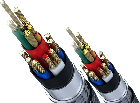
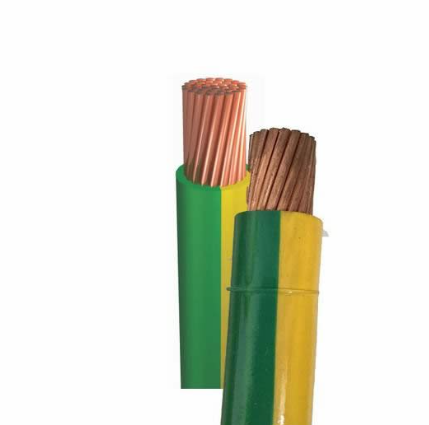
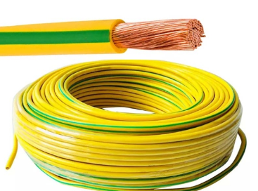
Typical color Green, green and yellow White, Blue
Fault Protection Function Is present (triggers the protection device to activate) Not present (merely serves as a current return path)

Common Misconceptions and Risks

Many people easily confuse the grounding wire with the neutral wire, and sometimes even use them interchangeably during wiring, which poses serious safety hazards:
  • If the neutral line is used as an earth wire, the operating current of the neutral line will flow through the grounding circuit during normal operation, causing the equipment casing to become energized and increasing the risk of electric shock.
  • If the grounding wire and neutral wire are connected in reverse, when a device fails, the fault current cannot be discharged promptly, preventing the protective device from operating and potentially causing equipment damage or electric shock accidents.
  • When the neutral wire is disconnected and used together with the grounding wire, it can induce phase voltage on the equipment casing, leading to severe electric shock accidents.
Therefore, in electrical wiring, the ground wire and neutral wire must be strictly distinguished, adhering to the principle that 'the ground wire is not operational when grounded, and the operational wire is not grounded.'

Structure of the grounding wire

Conductor type

  • Solid conductor: Consisting of a single metal wire, it exhibits high mechanical strength and resistance to oxidation, making it suitable for short-distance installation and fixed applications such as internal equipment grounding or small grounding terminal connections.
  • Multi-strand stranded conductor: Composed of multiple fine metal wires twisted together, it offers excellent flexibility, facilitating bending and long-distance installation. It is suitable for complex installation environments such as cable tray wiring and underground grounding grids.

insulation material

The insulation material of the grounding wire must possess excellent insulation properties, corrosion resistance, and mechanical strength. Common types include:
  • PVC (polyvinyl chloride): Low cost and excellent insulation properties, suitable for indoor use at room temperature.
  • XLPE (Cross-linked Polyethylene): High-temperature resistant, anti-aging, and possessing high mechanical strength, making it suitable for outdoor and high-temperature environments.
  • LSZH (Low Smoke and Halogen-Free): Produces minimal smoke and releases no toxic gases during combustion, making it suitable for densely populated areas (e.g., office buildings, subways) and enclosed spaces.

Armoring Option

To enhance the mechanical protection and interference resistance of grounding wires, armored structures are employed in certain applications.
  • Steel wire armor: Weaved from galvanized steel wire, it exhibits high mechanical strength and can withstand external impacts and rodent damage, making it suitable for underground installation and harsh outdoor environments.
  • Copper tape shielding: Features electromagnetic shielding capability to reduce external electromagnetic interference while enhancing corrosion resistance, making it suitable for grounding systems in communication equipment and data centers.

Typical voltage level

The voltage level of the grounding wire must match that of the corresponding power system:
  • Low-voltage grounding applications: Suitable for civil buildings and small industrial equipment with AC voltages below 500V, representing the most common usage scenario.
  • Grounding for medium-voltage systems: Suitable for industrial distribution networks and substations operating at 6 kV to 35 kV, requiring insulation materials and conductor materials that are resistant to high voltage and aging.

Selection and Specifications of Grounding Wires

Factors affecting cable specifications

When selecting the grounding wire specifications, the following key factors must be comprehensively considered:
  • Fault current magnitude: The greater the fault current, the larger the required conductor cross-sectional area, ensuring it can withstand instantaneous high currents without melting.
  • Failure duration: The longer the protection device operates, the better the grounding wire must be heat-resistant to prevent overheating damage.
  • Installation environment: For outdoor, humid, or corrosive environments, use corrosion-resistant materials (e.g., tin-plated copper or copper-clad steel); for high-temperature environments, select heat-resistant insulating materials.
  • Soil resistivity: The higher the soil resistivity, the poorer the current dissipation effect of the grounding electrode, requiring compensation by increasing the cross-sectional area of the grounding wire or the number of grounding electrodes.
  • Temperature rise limitation: When the grounding wire carries fault current, its temperature increase must be kept within the safe range to prevent insulation melting or conductor damage.

International specification standards

Different countries and regions have established clear specifications for grounding wires, with the most common types including:
  • IEC standards (International Electrotechnical Commission): IEC 60364 specifies grounding requirements for low-voltage systems, while IEC 60502 establishes structural and performance standards for cables.
  • The NEC Standard (National Electrical Code): Provides detailed requirements for the material, cross-sectional area, and installation method of grounding wires, with particular emphasis on safety performance.
  • IEEE Standard: IEEE 80 serves as the core guideline for grounding system design, applicable to industrial and power systems.

Practical Tips for Product Selection

Material selection: Prioritize copper conductors, especially in humid or corrosive environments or scenarios with stringent safety requirements (e.g., data centers, hospitals). For cost-sensitive applications with low fault currents, aluminum conductors may be used, but they require increased cross-sectional area and appropriate corrosion protection measures.
Environmental compatibility: For indoor dry environments, PVC insulated grounding wires are recommended; for outdoor or high-temperature environments, XLPE insulation is preferred; LSZH insulation must be used in densely populated areas.
Cross-sectional calculation: Determine the minimum cross-sectional area based on the fault current magnitude and duration, in accordance with local standards, to prevent the grounding wire from overheating and burning out due to an excessively small cross-section.

Installation method of the grounding wire

Underground installation

Underground installation is the most common grounding method, suitable for large grounding grids, substations, industrial plants, and similar applications.
  • Ground grid: A mesh structure woven from bare copper or tin-plated copper conductors, buried 0.51 meter underground, effectively reduces ground resistance and ensures uniform current dissipation.
  • Buried bare copper conductor: One or more bare copper conductors are buried parallel underground, suitable for long-distance or area grounding. During installation, avoid conflicts with underground pipelines or cables.
Key considerations for underground installation: Select areas with lower soil resistivity; if the soil resistivity is excessively high, measures such as soil replacement or addition of resistivity-reducing agents may be employed to reduce the grounding resistance. Conductor connections should be made using crimping or welding to ensure secure fixation.

Cable tray installation

In industrial plants, high-rise buildings, and similar settings, grounding wires are typically installed alongside power cables within cable trays.
  • During installation, ensure the grounding wire is reliably connected to the cable tray; the tray itself can serve as an auxiliary grounding conductor.
  • The grounding wire must be laid along the entire length of the cable tray and secured at regular intervals to prevent loosening caused by movement.
  • The insulation grounding wire must be maintained at a safe distance from other cables to prevent insulation damage that could cause short circuits.

Equilibrium Potential Connection for Equipment

Equilibrium potential bonding of equipment involves connecting the metal casings and frames of electrical devices through grounding wires to form a unified system, ensuring all equipment operates at the same potential level.
  • Motor and transformer: Connect the equipment casing to the grounding busbar via a grounding wire to ensure the casing remains unpowered during faults.
  • Switchgear: The metal frames of distribution cabinets and switchgear must be reliably connected to the grounding wire, and the grounding terminals of internal components must be uniformly connected to the grounding busbar.
  • During connection, remove the paint and oxide layers from the device housing, ensure the grounding wire makes tight contact with the metal housing, and reduce contact resistance.

New Energy System Grounding

With the development of renewable energy sources such as solar and wind power, grounding in new energy systems has become a critical priority:
  • Photovoltaic system: The metal frames and mounting brackets of photovoltaic modules must be connected via grounding wires, while the enclosures of inverters and combiner boxes should also be integrated into the grounding system to prevent lightning strikes and electrical leakage.
  • Wind power system: The nacelle and tower of wind turbines must be reliably grounded, and the lightning protection devices on the blades must conduct lightning currents into the ground via grounding wires.
  • New energy systems are typically deployed in outdoor environments, requiring corrosion-resistant and aging-resistant grounding wire materials (such as tin-plated copper or XLPE insulation).

Application scenarios for grounding wires

Residential buildings

In households and residential communities, the grounding wire is the cornerstone of electrical safety:
  • High-power appliances such as refrigerators, air conditioners, and washing machines all use three-prong plugs, with the longest pin connected to the ground wire to ensure that any live current from the device is quickly discharged into the earth.
  • The lightning protection grounding system and electrical grounding system of a building typically share a common grounding electrode. The grounding wire connects the roof lightning rod and metal components to this electrode, preventing damage to the building and its equipment from lightning strikes.
  • Moist areas such as bathrooms and kitchens must be connected to equipotential bonding. The faucets, metal pipes, and electrical appliance casings should be grounded via grounding wires to prevent electric shock caused by potential differences.

industrial factory building

In industrial production, electrical equipment is densely installed and operates at high power levels, making the grounding wire particularly critical:
  • The metal frames of large equipment such as machine tools and production lines must be reliably grounded to prevent electric shock accidents caused by leakage current during operation.
  • In harsh environments such as chemical plants and metallurgical facilities, grounding wires must possess corrosion resistance and high-temperature tolerance to prevent grounding failure caused by environmental factors.
  • In the power distribution system of the factory building, the grounding wire works in conjunction with protective devices to rapidly isolate short-circuit faults, preventing fault escalation that could disrupt production.

Distribution Network System

Urban distribution networks and substations are the core of power transmission, while grounding wires ensure the stable operation of the grid.
  • The substation's grounding grid is constructed from numerous braided bare copper conductors, covering the entire substation area and centrally connecting the grounding terminals of transformers, switchgear, and other equipment to ensure rapid fault current dissipation.
  • The towers of high-voltage transmission lines must be grounded. The grounding wire connects the tower to the grounding electrode, preventing the tower from becoming energized during lightning strikes.
  • The neutral line of the distribution network is grounded at the incoming point, working in conjunction with the grounding conductor to form a complete grounding protection system that stabilizes voltage and ensures safety.

Communication and Data Centers

Communication equipment and data centers demand exceptionally high standards for power supply stability and security:
  • The tower structure and equipment enclosures of communication base stations must be reliably grounded to prevent lightning strikes and electromagnetic interference, ensuring stable signal transmission.
  • Equipment such as servers and switches in data centers are connected to the equipotential bonding system via grounding wires to prevent damage to sensitive electronic components caused by static electricity or leakage current.
  • The grounding system of a data center must be designed in coordination with the lightning protection system and power supply system to ensure rapid power interruption during faults, thereby safeguarding equipment and data security.

Renewable Energy Project

The grounding systems of new energy projects such as solar power plants and wind farms have unique characteristics:
  • The photovoltaic modules of solar power stations are widely distributed and require a unified grounding network established through grounding wires to prevent lightning strikes and electrical leakage.
  • Wind turbine towers can reach heights of dozens of meters and are highly vulnerable to lightning strikes. The grounding wire must rapidly channel the lightning current into the ground to protect the power generation equipment inside the nacelle.
  • Most new energy projects are located in open outdoor areas where soil resistivity may be high. Therefore, resistance reduction measures (such as adding resistance-reducing agents or increasing the number of grounding electrodes) must be implemented to ensure effective grounding.

Color specifications for grounding wires

International Standard for Color Codes

To facilitate identification, there are internationally standardized regulations regarding the color of ground wires:
  • Core colors: green, green and yellow (yellow-green line);
  • The yellow-green dual-color scheme is the most commonly used color for grounding wires, widely recognized globally to identify dedicated grounding wires and must not be used for any other purposes.
  • A pure green grounding wire can also be used for grounding, but it must be distinguished from other colored wires.

Regional Difference Specifications

There are subtle differences in color standards across different regions and countries:
  • North America (NEC standard): The ground wire is typically green, green-yellow, or a bare conductor, while the neutral wire is white or gray.
  • Europe (IEC standard): Strictly specifies that the grounding wire shall be green and yellow, the neutral wire blue, and the phase wires brown, black, or gray.
  • China: In compliance with IEC standards, the grounding wire is colored in green and yellow, the neutral wire is light blue, and the phase wires are Phase A yellow, Phase B green, and Phase C red (or Phase A brown, Phase B black, and Phase C gray).

matters need attention

  • The color designation of the grounding wire is mandatory and must not be altered arbitrarily to prevent wiring errors caused by color confusion.
  • During actual installation, color requirements must be verified in accordance with local electrical codes to ensure compliance with regional standards.
  • For exposed grounding wires (such as bare copper grounding grids), although they lack color identification, their grounding function must be clearly determined based on the installation location and connection method.

Relevant Standards and Certifications

IEC standard

The grounding-related standards established by the International Electrotechnical Commission (IEC) serve as a crucial global reference:
  • IEC 60364: "Electrical Installations in Buildings" specifies the grounding methods, grounding resistance requirements, and safety protection measures for low-voltage systems.
  • IEC 60502: "Power Cables and Accessories with Extruded Insulation at Rated Voltages of 130 kV" specifies the structural, material, and performance requirements for grounding cables.
  • IEC 61558, "Safety for Power Transformers, Power Supply Equipment and Similar Products," specifies detailed requirements for the safety of equipment grounding.

IEEE standard

The standards of the Institute of Electrical and Electronics Engineers (IEEE) are widely adopted in industrial and power systems:
  • IEEE 80: "Guidelines for Grounding of AC Substations" is the authoritative guide for grounding system design, covering grounding grid design, grounding resistance calculation, safety assessments, and related topics.
  • IEEE 142: "Guidelines for Grounding of Industrial and Commercial Power Systems," applicable to the grounding system design of industrial plants and commercial buildings.

NEC standard

The National Electrical Code (NEC) imposes stringent requirements on grounding systems in North America:
  • specify the material, cross-sectional area, installation method, and connection requirements of the grounding wire;
  • Emphasize the importance of equipotential bonding, requiring its implementation in humid areas such as bathrooms and kitchens.
  • Specific specifications are provided for the grounding resistance values in different scenarios (e.g., residential, industrial, and commercial).

National Standard

China's grounding-related standards primarily refer to IEC standards and are formulated in accordance with domestic practical conditions:
  • GB 50057: "Code for Lightning Protection Design of Buildings" specifies the design requirements for lightning protection grounding of buildings.
  • GB 50169: "Code for Construction and Acceptance of Grounding Systems in Electrical Installation Projects" specifies the construction techniques and acceptance criteria for grounding systems.
  • GB/T 12706: "Extruded insulated power cables and accessories with rated voltages from 1 kV (Um = 1.2 kV) to 35 kV (Um = 40.5 kV)" specifies the technical parameters for grounded cables.

Certification Requirements

A qualified grounding wire must undergo relevant certification to ensure product quality and safety performance.
  • UL Certification: Certified by the Insurance Institute of America (IIA), applicable to the North American market, confirming compliance with NEC standards.
  • CE Certification: A mandatory EU certification that verifies compliance with IEC standards, enabling products to be sold in EU member states.
  • CCC Certification: China's mandatory product certification requires that grounding wires sold domestically must pass CCC certification to ensure compliance with national standards.
Conclusion
The grounding wire, serving as the "safety lifeline" of electrical systems, is of paramount importanceits significance cannot be overstated. It not only constitutes the final line of defense for personal safety but also plays a central role in ensuring stable equipment operation and preventing fire hazards and fault escalation. From residential buildings to industrial facilities, and from traditional power systems to renewable energy projects, grounding wires are ubiquitous in all applications.
Selecting appropriate materials and specifications for grounding wires, adhering to standardized installation procedures, and conducting regular maintenance and inspections are crucial for ensuring the effective operation of grounding systems. With technological advancements, intelligent grounding monitoring, eco-friendly materials, and advanced corrosion prevention technologies will drive grounding systems toward greater reliability, intelligence, and environmental sustainability.
In practical applications, it is imperative to strictly adhere to relevant standards and specifications, with particular emphasis on the design, installation, and maintenance of grounding systems. This ensures that grounding wires serve as genuine "safety guardians" for power systems, safeguarding both personnel safety and equipment stability.
 
Email
CopyRight © 1989 Chunbin Cable Co., Ltd.
Technical support :Coverweb
Fill in you have to consult
We will contact you as soon as we receive the inquiry and ensure the security of your information.
Name*
Email*
Phone
Country
Message*