What does the earth do in a cable?
When selecting cables for residential wiring, commercial building power distribution, factory equipment wiring, outdoor engineering projects and complete‑set‑equipment cabling, many purchasers, electrical engineers and field installers encounter a fundamental yet critical question: what exactly does the earth (ground) conductor inside a cable do? Many people simply equate the earth conductor with the neutral wire, or regard it as an optional auxiliary conductor. Some even remove the internal earth core of cables to cut costs. Such misconceptions create severe hidden dangers including electric shock, equipment burnout and electrical fire.
The earth conductor is a special conductor within multi‑core cables. Under most normal operating conditions, almost no operating current flows through it. It does not form part of the power supply circuit and remains in a standby state. Only when faults such as insulation failure, electric leakage, short‑circuit and surge occur will the earth conductor activate and deliver its core functions. Earthing design runs through the whole lifecycle of cable design, production, selection and installation, ranging from low‑voltage building cables and control cables to medium‑ and high‑voltage power cables. IEC international standards and national wiring codes impose mandatory requirements on the cross‑section, colour identification, material and earthing methods of cable earth conductors. This article fully explains the core functions of the earth conductor in cables, distinguishes protective earthing from functional earthing, clarifies the essential differences between earth conductor, neutral wire and cable shield, describes earthing arrangements for different cable types, sorts out selection pitfalls and practical engineering guidelines. It helps engineering contractors, buyers and electricians understand and apply cable earth conductors correctly so as to avoid electrical safety accidents.
Basic Concept: What Is the Earth Conductor inside a Cable
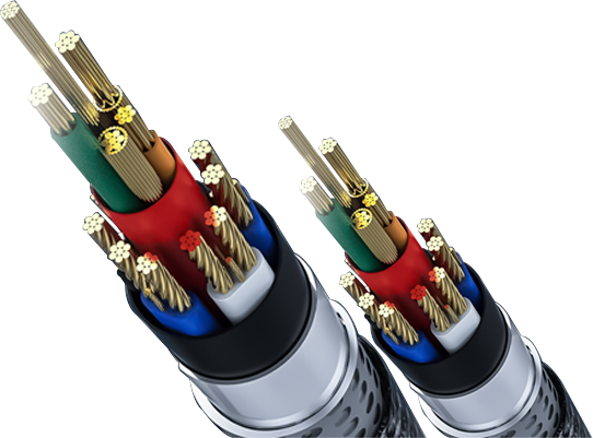
The earth conductor in cables is formally named Circuit Protective Conductor, abbreviated as CPC, commonly known as the PE protective conductor. It can be an independent insulated conductor inside multi‑core cables, a bare conductor, or utilise metallic armour and screen layers as the earthing path. According to globally accepted IEC colour codes, the dedicated protective earth conductor is insulated with green‑and‑yellow bi‑colour insulation. This colour is exclusively assigned to protective earth conductors and must never be used for live conductors or neutral wires, enabling installers to identify the protective earth quickly and prevent mis‑wiring accidents.
Cable structures vary across regions. In some BS‑standard twin‑and‑earth cables, the earth conductor is a bare copper conductor without insulation. At joints, installers must fit green‑and‑yellow insulating sleeves for identification. This is compliant under specific standards but does not mean earth conductors can be permanently exposed. Most earth conductors are copper‑based; aluminium conductors are adopted for certain large‑cross‑section engineering applications. The key requirement is low resistance to conduct fault current instantly during faults, together with sufficient mechanical strength to withstand thermal stress under short‑circuit conditions without burnout.
One widespread misunderstanding must be clarified: the earth conductor does not complete the power supply loop. The neutral wire (N) serves as the return path for the operating circuit and continuously carries load current during normal equipment operation. By contrast, the earth conductor carries almost no current in normal service and acts as an independent safety backup path. The two must never be mixed up, which represents one of the most frequent application errors in cable practice. One end of the earth conductor connects to metallic equipment enclosures and cabinets; the other terminates at the earthing busbar inside distribution panels and finally links to buried earth electrodes, establishing a reliable electrical connection among cable, equipment and earth.
Two categories of earthing exist within cables. Protective Earthing (PE) focuses on human‑being and equipment safety against leakage faults. Functional Earthing (FE) stabilises circuit potential and suppresses electromagnetic interference to secure stable operation of signal‑related equipment. They serve different purposes and follow distinct selection and installation rules and cannot replace one another.
Core Functions of Cable Earth Conductor: Protective Earthing (PE)
Protective earthing is the highest‑priority function of cable earth conductors and is mandated by all electrical codes. Its core principle is to build a discharge path with extremely low impedance. When cable insulation ages, abrades or gets damaged by high temperature, live conductors may contact cable metallic sheaths or equipment metal housings, resulting in earth faults. Equipment enclosures will then carry hazardous voltage. Without an earth conductor, operators touching metal housings will form a human‑body shock loop and suffer electric injury.
Prevent electric shock and trigger fast protective device tripping
When leakage faults occur, the built‑in cable earth conductor provides a path with far lower resistance than human bodies. Fault current flows preferentially to earth via the earth conductor. The substantial fault current triggers circuit breakers and residual‑current devices (RCDs) to trip within milliseconds and cut off the faulty circuit, preventing electric shock hazards for personnel touching live metal parts. If cables lack an earth core, equipment housings sustain dangerous voltage continuously without protective device activation, leaving persistent safety risks.
A common misconception needs addressing: the earth conductor does not “absorb” electricity into the ground. Instead, it offers the path of least resistance to guide fault current back to the power‑supply side and activate protective devices. Lower earth‑conductor resistance generates higher fault current and faster protective‑device response. This explains why international standards specify minimum cross‑sections for earth conductors. Earth cores shall not be arbitrarily downsized, nor shall thin wires substitute standard protective earth conductors.
Restrain fault propagation and reduce electrical‑fire risks
Electrical‑fault‑caused‑arc due to insulation breakdown is a major contributor to building fires. In case of phase‑to‑enclosure short‑circuits without reliable earthing, persistent electric arcs appear at fault points. High‑temperature arcs ignite cable sheaths, adjacent wiring and combustible building materials and trigger fires. A sound earth‑conductor path releases fault current promptly and prompts protective devices to de‑energise circuits, eliminating arc‑sustaining conditions and suppressing fire outbreaks. Earthing continuity tests are mandatory during acceptance of many overseas projects to verify intact earth paths free from disconnection or bad contacts.
Discharge surge and lightning‑induced current to protect cables and downstream equipment
Outdoor‑laid cables, photovoltaic cables and power cables for machinery are subject to lightning‑induced overvoltage. Grid switching and large‑equipment startup‑shutdown also produce transient surge voltages. Cable earth conductors divert such transient impulse currents to earthing systems and limit potential rise on cables and equipment enclosures, avoiding insulation breakdown and damage to downstream expensive apparatus such as motors, frequency converters and controllers. Note that ordinary protective earth conductors are not equivalent to dedicated lightning down‑conductors. Larger‑cross‑section dedicated earthing conductors are required for direct‑lightning‑stroke scenarios, which ordinary cable earth cores cannot handle.
Dissipate static electricity for flammable‑and‑explosive‑prone environments
In chemical plants, oil‑gas facilities and powder‑processing workshops, static charges accumulate on metal equipment connected by cables. Static‑charge build‑up may generate sparks and ignite flammable gas or dust mixtures. Cable earth conductors continuously drain static charges from metallic components to ground and eliminate static hazards. For such special conditions, complete earth cores are required. Moreover, metallic housings and armour along the whole cable route must be earthed to guarantee equipotential bonding.
Functional Earthing (FE) of Cable Earth Conductor: Secure System Operation
Beyond human‑safety‑oriented protective earthing, earth conductors in many power cables and shielded control cables undertake functional‑earthing tasks. Functional earthing is not primarily for shock prevention but ensures stable operation of circuits and signal systems, widely adopted in automation, communication and precision‑measurement equipment.
Establish stable zero‑potential reference
Earth itself acts as a huge body with stable potential. Cable earth conductors anchor the reference potential of electrical systems to ground and prevent potential drift. Without reliable earthing, potential differences emerge between multiple devices in complex industrial sites, leading to drifted measurement readings, abnormal PLC logic, servo‑system errors and unstable equipment performance. Reliable functional earthing serves as the foundation for accurate signal acquisition for analogue‑signal cables.
Enable electromagnetic shielding and reduce interference
Shielding performance takes effect only when cable shields are earthed. External electromagnetic interference hits metallic shields; induced interference charges flow to earth via earth conductors and avoid coupling into internal signal wires. Meanwhile, electromagnetic noise generated inside equipment is contained by shields and prevented from radiating outward to disturb nearby apparatus.
Differences in practical earthing for various cables should be noted. For low‑frequency analogue‑signal control cables, single‑end earthing of shields is generally recommended to avoid ground‑loop‑induced power‑frequency interference. Metal shields of high‑voltage power cables usually require earthing at both ends to suppress induced over‑voltage. High‑frequency signal cables shall follow corresponding product specifications. Importantly, shield earthing cannot replace independent PE protective conductors. Cable shields normally feature small cross‑sections and cannot withstand large leakage‑fault current. Shields will burn out under faults if used as protective earth paths. Protective‑earth conductors and shield‑earthing paths must remain separate.
3.3 Realise equipotential bonding
All metallic components within a system, including cable armour, equipment enclosures, cabinets and metal cable trays, are interconnected through the earthing network. All metallic parts maintain identical potential. Even during faults, hazardous potential differences between metallic components are eliminated, together with touch‑voltage and step‑voltage risks. Equipotential bonding is compulsory for industrial plants and hospital power‑distribution systems.
Critical Comparison: Earth Conductor, Neutral Wire and Cable Shield
Confusion between earth conductor, neutral wire and shield frequently occurs in cable technical documents, overseas inquiries and on‑site projects. Incorrect core‑count specifications during purchasing lead to non‑compliant cables on‑site. Below is a clear comparison covering functions, current characteristics, colour codes and substitutability
Protective Earth PE (Earth / CPC): Safety‑oriented protective conductor. Almost zero current under normal conditions; fault current flows only during leakage or short‑circuit events. Core purposes: personal‑safety protection, surge and static discharge. Colour: green‑and‑yellow. Connections: equipment enclosures, earthing busbars. **Must never be used as a working‑circuit conductor**.
Neutral Wire N: Working‑return conductor. Carries continuous operating current under normal conditions; also bears unbalanced current under three‑phase unbalance. Core purpose: complete power‑supply loops for equipment operation. Colour: light blue (IEC standard). Connections: return path to transformer neutral point. Neutral and earth conductors are bonded only at the main power‑supply point; neutral‑earth mixing is forbidden further downstream.
Cable Shield: Electromagnetic‑interference‑suppression structure. Almost no current under normal conditions; discharges induced charges when earthed. Core purpose: block electromagnetic interference. Materials: copper foil, copper‑wire braid. Generally small cross‑section. **Cannot replace PE protective earth for large‑fault‑current handling**, for shielding purposes only.
Earth‑conductor Implementation in Different Cable Types
Earth conductors are not always independent insulated wires. Earthing paths are realised differently across cable constructions, which is essential knowledge for cable selection.
First type: independent insulated earth core. The most common configuration found in multi‑core power cables such as YJV and RVV. Apart from phase and neutral cores, a dedicated green‑and‑yellow insulated PE conductor is fitted. This structure applies to most residential, commercial and industrial applications. PE‑conductor cross‑sections comply with IEC and national standards: where phase‑conductor size ≤ 16 mm², earth conductor matches phase‑conductor cross‑section; phase‑conductor size between 16 mm² and 35 mm², earth conductor takes 16 mm²; phase‑conductor size > 35 mm², earth‑conductor cross‑section equals half of phase‑conductor cross‑section and shall not be less than 16 mm². Earth‑conductor dimensions shall not be arbitrarily reduced during procurement. For BS‑standard twin‑and‑earth cables, the earth conductor is bare copper; green‑and‑yellow heat‑shrink sleeves must be fitted at joints for identification, which is permitted under relevant standards yet bare exposure of terminals is prohibited.
Second type: armour‑served earthing path. Metallic armour in steel‑tape‑armoured and steel‑wire‑armoured cables (e.g. YJV22) provides mechanical protection and may act as an auxiliary earthing path on condition of full electrical continuity and reliable earthing at both cable ends. Nevertheless, most specifications still require an independent internal PE core. Armour shall serve only as supplementary earthing and must not substitute dedicated protective conductors entirely. This is a frequent pitfall for overseas projects, where clients mistakenly assume armour earthing removes the need for PE cores.
Third type: shield‑based earthing. Braided shields in control and instrument cables achieve functional earthing for anti‑interference purposes. **Shields cannot function as protective earth conductors**. Equipment enclosures still require separate PE connections.
Fourth type: dedicated earthing cables. Products such as bare‑copper strands and single‑core green‑and‑yellow earthing wires are used for main earthing trunking and equipment earthing branches.
Common Earth‑conductor Mistakes and Resulting Risks
Errors related to earth conductors during cable selection and field installation nullify system‑safety design and represent major causes of overseas‑project acceptance failure.
1. Removing earth cores to cut costs by specifying cables without PE conductors. In leakage‑fault scenarios, equipment housings become live without protective‑device tripping, posing severe electric‑shock risks and violating IEC and national wiring codes. Such cables may work temporarily but leave persistent safety hazards.
2. Undersized earth‑conductor cross‑sections. Buyers focus merely on phase‑conductor sizes while specifying insufficient earth‑conductor gauge. High earth‑path impedance limits fault current, preventing circuit breakers from fast tripping. In extreme cases, earth conductors overheat and melt, eliminating protection.
3. Using earth conductors as neutral wires or mixing neutral‑earth connections. Green‑and‑yellow earth conductors carry operating current. Potential rises on earth paths energise all connected metal housings and trigger continuous RCD tripping.
4. Using shields or armour as full substitutes for independent PE cores. Shields feature small cross‑sections and burn out instantly under short‑circuit faults, breaking earthing continuity. Broken armour joints also disable earthing paths.
5. Poor connections or broken earth conductors. Even with correctly‑specified cable earth cores, bad crimping, loose terminals or intermediate breaks render earthing ineffective. Earthing‑continuity tests are compulsory for project acceptance.
6. Improper shield‑earthing practice. Dual‑end earthing of control‑cable shields with unequal‑potential earthing points produces circulating currents inside shields and introduces heavy power‑frequency interference, resulting in signal distortion and equipment malfunctions. Many automation‑site debugging problems originate from this mistake.
Practical Earth‑conductor Selection Guidance for Typical Application Scenarios
Low‑voltage power distribution for residential & commercial buildings
Socket circuits must be equipped with independent green‑and‑yellow PE cores. Mains‑flex cables for portable appliances shall not omit earth conductors. Within TN‑S systems, phase, neutral and PE conductors inside cables remain fully separated without combination. For overseas‑project procurement, verify that earth‑conductor cross‑sections comply with local wiring regulations.
Industrial power‑equipment cables (motors, frequency converters)
Multi‑core power cables shall incorporate independent PE protective cores. Where metallic shields are present, shields are used solely for functional anti‑interference earthing. Equipment metal housings rely on PE cores for fault protection. Frequency‑converter output cables demand special attention to earthing; poor earthing causes electromagnetic leakage disturbing adjacent instruments.
Control and signal cables
Select single‑end or double‑end shield earthing according to signal types. Shields are not protective earth replacements. Metal enclosures for control cabinets and field sensors shall connect to dedicated PE conductors.
Armoured buried cables
Armour shall be earthed at both ends but must not replace internal PE cores. Corrosion protection for conductors shall be considered for underground installation to guarantee long‑term earthing integrity.
New‑energy cables for photovoltaic and wind‑power systems
Complete earthing arrangements apply to both DC and AC sides of photovoltaic systems. Module frames and inverter enclosures shall connect to earth conductors. Follow photovoltaic‑industry standards for earth‑conductor sizing; do not down‑specify earth cores arbitrarily.
Flammable‑and‑explosive‑prone hazardous locations
Maintain full continuity of earth conductors. Cable trays and armour shall implement equipotential bonding. Avoid intermediate earth‑conductor disconnection. Conduct earth‑resistance tests to satisfy explosion‑proof‑code requirements.
Conclusion
Superficially, earth conductors inside cables appear idle and carry negligible current under normal operation without participating in power delivery. Nevertheless, they constitute an indispensable safety line of defence for electrical systems. Cable earth conductors fall into protective earthing (PE) and functional earthing (FE). Protective earthing provides low‑impedance discharge paths during leakage faults to protect personnel from electric shock, suppress arc‑ignited fires and dissipate static and surge energy. Functional earthing establishes stable potential references and enables electromagnetic shielding to support reliable operation of precision signal equipment.
Bear in mind that earth conductors are not neutral wires, and cable shields cannot replace dedicated protective‑earth cores. During cable selection, confirm availability of independent PE cores and verify earth‑conductor cross‑sections against applicable standards. Secure proper connections on‑site and avoid loose joints or breaks. Complete earthing‑continuity tests upon project acceptance. For residential, commercial, industrial and export‑oriented projects alike, proper understanding, selection and installation of cable earth conductors are essential to realise their protective value and avoid electric‑shock and fire incidents.